(214) 766-4922
Feritscope | Ferrite Content
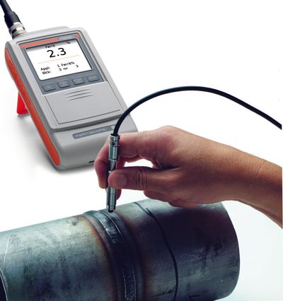
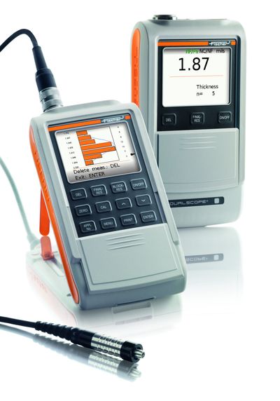
Fischer Feritscope® FMP30C

Fischer Feritscope® FMP30C
We understand Ferrite! Call us and ask. 214-766-4922
Currently in STOCK.
Ferrite content is an important consideration in Stainless, Duplex Stainless Steels and general welding as it effects corrosion resistance and susceptibility to cracking. Low or lack of ferrite, for example around weld seams, leads to significant structural weaknesses in austenitic and duplex steels. Too much ferrite content, on the other hand, reduces corrosion resistance, toughness and ductility. Feritscope application can be critical to know. The Fischer Feritscope® FMP30C offers precise measurement instruments with which you can determine the proportion of ferrite quickly and non-destructively. VSI is your technical expert on Fischer Feritscope®.
Austenitic or duplex steels must withstand heat, saltwater, water, harsh enviroments, aggressive substances and high pressure, ferrite content plays a significant role. Especially when measurements are in chemical plants, energy utilities, oil tanker, oil tanks and process engineering plants, the advantages of the Fischer handheld devices become very evident. A range of probes are available for the FERITSCOPE® FMP30C, with which you can reliably determine ferrite content, even in hard-to-reach areas.
Simple and Quick Measurements
It is easy to measure the ferrite content accurately when using the FERITSCOPE FMP30. Upon probe placement on the surface of the specimen, the reading is displayed automatically and stored in the instrument. The probe can also be placed onto hard to reach areas. For such applications, the instrument features an “external start” function to trigger the measurements with the push of a button. This is ideal for measurements in pipes, bore holes or grooves.
Finding weld seams in polished surfaces is made easy through the “continuous display” instrument function. When scanning the surface with the probe with this function enabled, the continuous readings are displayed only. A change in the ferrite content reading indicates that the weld seam has been found. For easy ferrite content measurements along a weld seam, the instrument offers the “continuous measurement capture” function. When scanning the weld seam with the probe positioned, the continuous readings are captured and stored. This provides a ferrite content profile along the weld seam.
Measurement influencing factors do not significantly affect the FERITSCOPE FMP30. Ferrite content measurements can be carried out regardless of the substrate material properties starting at a plating thickness of 3 mm. Corrective calibrations with customer-specific calibration standards or correction factors (included) can be used to take influences of the specimen shape (strong curvature), plating and substrate thicknesses into account. The calibration is always stored measurement-application specific in the respective application memory.
Features
- Robust device for fast and exact determination of ferrite content onsite
- Color Display
- Display of the measured value in ferrite percentage (% Fe) or as ferrite number (FN)
- Large and easily readable display with comprehensive functions
- Measures automatically as soon as the probe is applied or with a millisecond delay
- Various probes available for reliable measurement even in hard-to-reach areas
- Full set of ferrite range standards for calibration.
- Just one calibration required for the entire measurement area
- Also available as a module with full functionality for the stationary measurement instrument MMS® PC2
- Built in stand
- Measurement capture
- Fast measurement and data storage
- Automatic measurement acquisition upon probe placement or through “external trigger”
- Enabled or disabled acoustic signal
- Overwriting of erroneous measurements or previously stored readings
- Adjustable tolerance limits
- Measurement data presentation as an analog bar with display of specification limits
- Continuous display: Continuous display of the reading when probe is placed on the specimen;storing with externally triggered measurement acquisition
- Outlier rejection function for the automatic elimination of erroneous measurements
- Matrix measurement mode: Measurement data storage in blocks that are set up in the application in the form of a matrix. Block change manually or automatically in the specified sequence
- Measurement data averaging: Only the mean value of a specified number of single readings is stored
- Automatic block creation: Number of single readings per block
- Area measurement: Continuous measurement acquisition until the probe is lifted off; only the resultant mean value is stored
- Continuous measurement acquisition and storage
Data Memory
- Up to 20,000 readings and 100 applications for measurement data and application‑specific calibrations
- Separation of the measurement data in up to
- 4,000 blocks
- Date and time stamp for the blocks
Evaluation
- Statistical evaluation of measurement series with mean value, standard deviation, max and min value, range
- Computation of the process capability indices cp and cpk
- Output of characteristic variance‑analytical values
- Graphical measurement presentation as a histogram with a Gaussian bell curve
Interfaces
- USB port for data transfer to a PC or printer
- Optional Bluetooth® module, interface for wireless data transfer to a PC (up to 10 m)
- Optional COM module, serial interface for data transfer to a PC or printer (cable length up to 12 m)
Calibration
- Only one calibration required for the entire relevant measurement range from 0.1 to approx. 90 FN.
- Adherence to the measurement accuracy specified in standard ANSI/AWS A4.2M/A4.2:1997
- Calibration using calibration standards traceable to TWI secondary standards or customer‑specific standards
- Linking applications: Common normalisation/calibration of applications
Calibration / Standards
To obtain comparable measurement results, the instruments must be adjusted or calibrated using standards that can be traced to internationally recognized secondary standards. For this purpose, the IIW (International Institute of Welding, UK) developed secondary standards that have been determined by the TWI (The Welding Institute, UK) according to the method described in DIN EN ISO 8249 and ANSI/AWS A4.2.Helmut Fischer offers certified calibration standard sets that are traceable to the TWI secondary standards for corrective and master calibrations. The standards of the FISCHER calibration standard sets list in addition to the ferrite numbers FN also the % Fe values. Influences including the shape of the part to be measured (strong curvature, thickness of the ferrite-containing coating, etc.) can be taken into account through corrective calibrations with customer-specific calibration standards or through correction factors (included). The normalization and corrective calibration are stored application-specific in the respective application memory of the instrument.
Magnetic Induction Method
The FERITSCOPE FMP30 measures according to the magnetic induction method. A magnetic field generated by a coil begins to interact with the magnetic portions of the specimen. The changes in the magnetic field induce a voltage proportional to the ferrite content in second coil. This voltage is then evaluated. All magnetic portions in the otherwise non-magnetic structure are measured, i. e., in addition to delta ferrite and other ferritic portions also strain-induced martensite, for example.
A specific advantage of the magnetic induction method for measuring the ferrite content is that a sigma phase, i. e., a Fe-Cr precipitation, which has formed due to excess ferrite content and unfavorable cooling conditions, for example, is recognized correctly as a non-ferritic structural component. In comparison, erroneous interpretation of ferrite content is likely in a section where a sigma phase is not easily distinguished from a ferritic structure.
Common Questions
N E E D T O K N O W
In order to meet and/or maintain most quality programs your quality control equipment, statements of calibration or calibrations must be performed every 6 to 12 months. We follow the manufactures procedures for calibration and can offer 17025 certs.
VSI can provide 17025 calibrations if needed and follows original manufacturer's specifications.
We have recently implemented GageTrak to provide more in-depth certifications and tracking information.
All of the instruments certified will be within the original manufacturer's specifications. The instrument's calibration function has been checked my performing a test calibration using precision secondary thickness standards which are traceable to the National Institute of Standards which are traceable to the National Institute of Standards and Technology (NIST). The test calibration was found to be capable of producing measurements accuracy of the standards measurement within an interval of ± 5%.